
This installment of Discovering Reason is adapted from my book, Power Tools for Reason 2.5, and describes how to create a high pass filter using the BV512 Digital Vocoder. This is an independent insert effect controlled by cutoff frequency and resonance sliders, and the parameters can be automated with a sequencer track or modulated by CV sources. When filtering a signal though the BV512, the results are not perfect, however in the right situation, the configuration can create some unique effects. The audio and CV modulation principles used in this project demonstrate some alternative ways of using the BV512 CV modulation features.
NN-XT High Pass Filter
There is an alternative method of processing sounds through a high pass filter, and before proceeding with the project, I’ll briefly explain how this is achieved. First, you need to solo out the signal that you want to filter. Now, render this signal to an audio file using the export loop or export song feature. Create a NN-XT and load the audio file into a sample zone. Program the sequencer to trigger the sample, and during sample playback, the signal can be processed using the NN-XT LP12 filter. This is a tedious process, but it provides the best results possible without using other software or hardware. If you are willing to sacrifice some audio quality, then the 24dB high pass filter configuration is an interesting alternative.
Example file: tedious_hp_method.rps
How the High Pass Filter Works
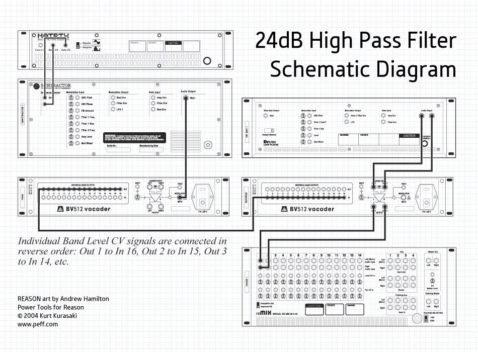
The high pass filter configuration starts with raw, unfiltered white noise generated by a Subtractor synthesizer. The Subtractor audio output is connected to the modulator input of a BV512 Vocoder in 32-band mode. White noise is analogous to “white light,” the mix of all colors in the visual spectrum. Likewise, combining all frequencies in the audio spectrum creates white noise. When the BV512 receives white noise on the modulator input, all vocoder bands open, because equal amounts of all frequencies are present.
Sweeping the LP24 cutoff frequency closes the vocoder filters from the high frequency bands down to the low frequency bands. In essence, the BV512 filter bands mimic the behavior of the Subtractor LP24 filter, and carrier signals will be filtered like a low pass filter.
A second BV512 Vocoder, set to FFT mode, is added to the rack, and the Individual Band CV Outputs of the first BV512 are connected in reverse order to the Individual Band CV Inputs on the second BV512 Vocoder. The reverse cabling causes the second vocoder to mirror the LP24 behavior, and the filters close from the low frequency bands up to the high frequency bands. Carrier signals processed through the second BV512 are filtered like a 24dB high pass filter.
Click image for larger version
Creating the High Pass Filter Effect
The schematic (above) presents a clear overview of the device cabling. The high pass filter is comprised of several different stages, and the directions are grouped to specify the connections and parameter settings of each stage. An example RNS file is provided below, but you should try building the effect yourself.
- Start with an empty rack, and create a Mixer
- Set the Song Tempo to 130 BPM
White Noise Modulator Signal Source
- Bypass Auto-Routing (hold down the shift key) and create a SubTractor Synthesizer
- Set the SubTractor Polyphony to 1
- Enable the Noise Generator
- Set the OSC Mix to 127
- Set the Filter 1 type to LP24
- Set the Amp Envelope attack to 0, decay to 0, sustain to 127, and release to 10
- Set the Velocity to F.Env modulation to 0
- Set the Master Level to 100
- Create a Matrix Pattern Sequencer connected to the SubTractor Sequencer Control Inputs
- Set the Matrix Pattern length to 1 Step, and program a tied gate event on Step 1
Carrier Signal Source The Dr.REX loop provides a source to demonstrate the filtering, and can be replaced with any mono or stereo audio signal source.
- Bypass auto-routing and create a Dr.REX Loop Player
- Load the ReCycle Loop, “130_NuYork_mLp_eLAB.rx2” from the from Reason Factory Sound BankMusic LoopsVariable (rx2)Uptempo Loops directory
- Set the Dr.REX Master Level to 108
- Copy the REX slice data to the Dr.REX 1 Sequencer Track
Carrier Vocoder Section
- Bypass auto-routing and create a BV512 Digital Vocoder
- Connect the Dr.REX Audio Outputs to the BV512 Carrier inputs
- Connect the BV512 Carrier outputs to the Mixer Channel 1 Inputs
- Rename “Vocoder 1” BV512 to “Reverse”
- Adjust the following parameters on the BV512:
| Reverse BV512 Vocoder Settings | |
|---|---|
| Mode | Vocoder |
| Band Count | FFT(512) |
| Hold | Off |
| Attack | 0 |
| Decay | 0 |
| Shift | 0 |
| HF Emphasis | 0 |
| Dry/Wet | 127 |
| Band Levels |
Modulator Vocoder Section
- Bypass auto-routing and create a second BV512 Digital Vocoder
- Rename the second vocoder to “Main”
- Connect the SubTractor Audio output to the “Main” BV512 Modulator Input
- In reverse order, connect all 16 Individual Band level Outputs from the “Main” BV512 to the Individual Band level Inputs on the “Reverse” BV512. In other words, connect Individual Band Level Out 1 to Individual Band Level In 16; Band Out 2 to Band In 15; Band Out 3 to Band In 14; etc.
- Adjust the following parameters on the “Main” BV512:
| Main BV512 Vocoder Settings | |
|---|---|
| Mode | Vocoder |
| Band Count | 32 |
| Hold | Off |
| Attack | 0 |
| Decay | 0 |
| Shift | 0 |
| HF Emphasis | 0 |
| Dry/Wet | 127 |
| Band Levels |
Run the sequence.
As the loop plays, adjust the Subtractor Filter 1 cutoff frequency to sweep the high pass filter. Because the modulation is reversed, a filter cutoff setting of 127 is fully open, and decreasing the filter cutoff will sweep the high pass filter up. You will first notice that the audio contains artifacts caused by the chaotic levels of the noise modulator source, and as indicated earlier, this effect may not be suitable when audio quality is important.
Example file: BV512-HP24Filter.rns
BV512 Envelope Settings
The chaotic impulses of white noise cause the BV512 band levels to jump around erratically. At the expense of increasing response time, a longer decay time smoothes out the glitchy artifacts. Increasing the “Main” BV512 decay time to 54 or greater will smooth these out. If you use the high pass filter for fast sweeps or gating, lower decay settings are recommended.
Different Filter Types
Using the spectrum analyzer, compare the Subtractor filter to LP12 response with the LP24. You can see how the LP24 band reject response is sharper than the LP12 filter type. You can also create a 36dB filter with a very steep cut by enabling Subtractor Filter 2 with Link on, and setting the cutoff frequency to 0. Also, the “Main” BV512 Vocoder can be used as a low pass filter to create a merging filter sweep effect where two signals are cut and open simultaneously with one being filtered down and the other filtered up.
Example File: BV512-HP36vLP36.rns
Resonant High Pass
Adding resonance to the high pass filter will sound a bit harsh because the resonance spike will overload the BV512 modulator input. Compensate for the resonance gain by reducing the Subtractor Master Level. For example, set the Master Output Level to 42 and set the Filter 1 Resonance to 100. For other settings, balance the two controls so that the modulator signal peaks do not overload the inputs and vocoder band levels
LFO Modulation
Filter 1 can be modified by any of the Subtractor modulation sources, and the filter modulations subsequently affect the high pass filter. Try the following modification to create a tempo synchronous sweep using LFO1:
- Start with the 24dB High Pass Filter Configuration from above
- Modify the following Subtractor Parameters:
- Filter 1 Cutoff Frequency to 63
- Select the ramp wave form (3)
- Enable LFO 1 Sync
- Set the Rate to 4/4
- Set the Amount to 120
Run the sequence
Example File: BV512-HP24_LFO.rns
Envelope Controlled High Pass Filter
Using a gate CV from a Matrix connected to the Subtractor Filter Envelope Gate Input, you can create a pattern controlled high pass filter. Rhythmic patterns programmed on the Matrix will trigger the Filter Envelope without interrupting the white noise signal.
- Start with the 24dB High Pass Filter Configuration from above
- Modify the following Subtractor Parameters:
- Filter 1 Cutoff Frequency to 127
- Filter Envelope A: 16, D: 85, S: 105, R: 41
- Filter Envelope Invert: On
- Filter Envelope Amount to 127
- Bypass auto-routing and create a second Matrix Pattern Sequencer
- Rename the Matrix to “PCF Gate”
- Connect the “PCF Gate” Matrix Gate CV output to the Subtractor Filter Env. Gate Input
- Program tied gate events on steps 1, 2, 5 and 6
- Program normal gate events on steps 3, 8, 9, 11, 13, 14, 15, and 16
Run the Sequence
The high pass filter adds a new twist to pattern controlled filtering because it uses inverse envelope modulation. The envelope parameters on the “Main” BV512 can be used to further shape the response of the PCF. Zero attack and zero decay times lend to very sharp patterns, but a decay setting of 30 or greater adds an interesting lag to the effect.
Example File: BV512-HP24_PCF.rns
Text & Music by Kurt Kurasaki


