
Phase Modulation is a brilliant method of synthesis championed by Casio in the 1980s. It enables a digital (or hybrid analogue/digital) synth to generate an enormous diversity of sounds – ranging from traditional analogue to FM in character – using a minuscule amount of wave memory and, by modern standards, minimal processing power. This made it possible for the company to develop a family of polysynths that were cheaper than almost anything that had come before, but were more flexible than pure analogue synths costing many times more. For people who thought of the CZ series as the "poor man's DX7" and didn't rate them very highly, they proved to be surprisingly successful. For people who understood them fully and knew how good they could sound, they proved to be surprisingly unsuccessful. But what, exactly, was Phase Modulation? To answer this, we need to delve briefly into the realms of geometry. (I could explain it with pure maths, but you'll prefer the geometry, believe me.)
Bending a sine wave

Figure 1: A sine wave
Take a look at the sine wave shown in figure 1. If you imagine sampling this at regular intervals along its length, it seems intuitively obvious that you could store these samples in a small ROM and later read them out in a steady stream to recreate the waveform. (Please, let's not get embroiled in silly arguments about digital waves looking and sounding like staircases, and stuff like that. They are all rubbish.) I have illustrated the sampled wave in figure 2.

Figure 2: A sampled sine wave
Now let's imagine the situation where the samples are not read from the ROM at a constant rate. Imagine what would happen if the first batch of samples (shown in green in figure 3) were read back very quickly, and the highest value sample (shown in red) was then held for a long period. The black line in the figure shows the result of this.
Now I'll do the same for the next group of samples, reading these out very quickly until I reach the one with the lowest value, and I'll then hold this. (Figure 4) I'm sure that you can see where I'm going with this, but I'll complete the description. We just keep reading out the green samples very quickly, while pausing for an appropriate length of time on the samples with the maximum and minimum values. The result is a surprisingly accurate representation of a square wave (figure 5) that I created simply by altering the rate at which the system read the sine wave's samples. This is Phase Modulation!

Figure 3: Reading out the first few samples at different rates.

Figure 4: Reading out some more of the samples

Figure 5: A Phase Modulation square wave
Creating some other waveforms
The black line in figure 5 is the waveform that you hear, not the one that describes the changes (or 'distortion') in the clock rate. But working this out is not difficult. When the clock rate is high, the samples are read out very quickly (which creates the almost vertical lines in the figure) and when the clock rate is almost zero, the same value is held for a long time (which is what happens at the top and bottom of the square waveform). So we can draw the changes in clock rate that generate an audio square wave as shown in figure 6.

Figure 6: The clock speed changes that generate the square wave in figure 5
Of course, there are many other clock rate distortions, and Casio chose eight shapes that created the eight waveforms available on the CZ synthesisers. I have shown another in figure 7, which would generate something akin to a sawtooth wave.

Figure 7: The clock speed changes that would generate a sawtooth wave
Controlling the Phase Modulation
Imagine that you are reading out the sine wave in the ROM at a steady rate. The result is, of course, a sine wave, a waveform with a fundamental frequency but no higher harmonics. Now imagine that you read the sine wave out of the ROM using the changes in clock speed illustrated in figure 7. The result is now a sawtooth wave that is rich in harmonics. But now ask yourself what you would obtain if you used the same shape of clock rate distortion but with reduced amplitude so that it didn't affect the clock rate quite as much. It would seem reasonable to guess that the resulting audio waveform would lie somewhere between the sine wave and the sawtooth wave. If you guessed this, you guessed right, because this is exactly what you obtain.
Remarkably, (or maybe not, because Casio's engineers are clever chaps) the resulting 'in between' waveform is all but identical to the wave that you obtain when you pass a sawtooth wave through a low-pass filter. This is a wonderful result, because it means that you can imitate the sweep of an analogue low-pass filter by controlling the amplitude of the clock rate distortion. Consequently, we can reduce Phase Modulation to two simple rules:
- The shape of the clock rate distortion determines the nature of the audio waveform that is generated.
- The amplitude of the clock rate distortion determines the harmonic content of the audio waveform that is generated.
This explains why Casio's CZ-series synthesisers had no filters. They didn't need them! Instead, a contour generator altered the amplitude of the clock rate distortion applied. To illustrate this, I have drawn figure 8, which shows what happens when an ADSR contour generator modifies the amount of the type of clock rate distortion that generates a square wave.

Figure 8: Using Phase Modulation to imitate an analogue low-pass filter
Creating a Phase Modulation sound
Perhaps the simplest, and one of the most effective polysynth sounds is the so-called PolyBrass patch. On an analogue synth, you create this by passing a sawtooth wave through a low-pass filter whose cut-off frequency is controlled by an ADSR contour generator. I have drawn the block diagram for this in figure 9. The cyan arrows represent the audio signal, while the red lines and arrows represent the control signals being applied to the VCO, VCF and VCA, respectively.

Figure 9: Creating an analogue PolyBrass patch
The equivalent block diagram for a Phase Modulation PolyBrass patch uses many of the same elements, but the configuration is different, as shown in figure 10. Most significantly, the ADSR contour is no longer affecting a filter because there isn't one; it's affecting the amount of clock rate distortion. So let's now create a Phase Modulation PolyBrass patch using Thor…

Figure 10: The Phase Modulation PolyBrass patch
Let's start with the Phase Modulation oscillator itself. Insert one of these in the Osc 1 position, and select the sawtooth wave as the 'First' wave. Set the 'Second' wave to OFF. (Don't worry about the Second wave; I will explain this in the next tutorial.) Set the keyboard tracking, octave, detune and fine tuning to their usual starting positions: KBD = 127, OCT = 4, SEMI = 0 and TUNE = 0. (See figure 11.) Now look at the bottom of the oscillator. You'll see a knob there that's called PM. This sets the initial amount of Phase Modulation. Turn this fully anti-clockwise to zero. Next, so that you can hear something, set up the Amp Env with instant Attack, instant Decay, maximum Sustain, and instant Release – in other words, a 'square' organ envelope. The sine wave in the ROM is being read out linearly so, as you can hear the tone is a pure tone, totally lacking any form of movement or timbral change:

Figure 11: The Pulse Modulation Oscillator
You'll have noticed that there is an annoying click at the start and end of each note. This is not an error; it is a consequence of the super-fast Amp Env that Thor can generate. We eliminate these clicks by slowing the Attack a little, and adding a short Release. I find that an Attack of around 20ms and a release of about 160ms do the job very nicely, as shown in figure 12. This produces Sound #2. It's not very interesting is it?
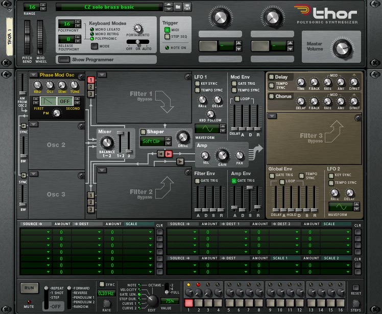
Figure 12: A basic patch with a PM oscillatorLet's now apply some clock rate distortion. Since there's no filter inserted into the patch, I'm free to use the Filter Env, and the shape that I'm going to use will be very similar to that shown in figure 8. The actual settings appear in figure 13, and if you want to recreate this contour precisely, the values I chose for the A, D, S and R stages are 233ms, 1.6s, -13.4dB and 229ms, respectively.

Figure 13: Contouring the sound
Hang on a second… this won't do anything because I haven't applied the Filter Env to the oscillator clock. To do this, I use the Modulation Matrix, directing the Filter Env to the Osc 1 PM Amount. Remember the second of the two rules above: the amount of clock rate distortion determines the harmonic content of the audio wave that is created, so the value inserted in the Modulation Matrix will determine how 'brassy' the sound will be. I have chosen an overly bright, obviously synthesised setting of 94. You can see the modified patch in figure 14, and hear its output as Sound #3. If you would prefer a more muted and perhaps more realistic sound, just reduce the modulation amount until you're happy with the results:

Figure 14: Adding clock rate distortion (Phase Modulation) to the patchIf you grew up in the 1970s, you'll recognise Sound #3 immediately. It's a single oscillator monosynth, with a timbre similar to something like one of the smaller ARPs. Except, of course, that it isn't an analogue or even 'virtual analogue' sound; it's generated by a digital algorithm. This is indeed a remarkable result but, while the timbre is self-evidently brassy, two important elements are still missing. Firstly, I need to add a little delayed vibrato to inject movement into the sound. Secondly, I need to add reverb. (Even the best monosynths are unable to produce convincing brass sounds without reverb.)
I'll apply vibrato using LFO1, utilising a sine or triangular waveform with a rate of around 5Hz, and a delay of around half a second. I can direct this to the pitch of Osc 1 by adding a second element in the Modulation Matrix. A small amount of modulation is appropriate, and this now gives us the patch in figure 15 and Sound #4:
Now I'll add the reverb. As usual, I am going to use Reason's RV7000, selecting a Long Hall from the factory presets, resulting in Sound #5:
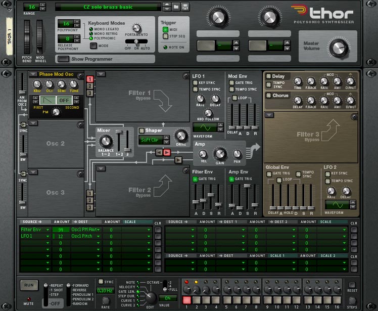
Figure 15: A solo brass patchOf course, Thor isn't limited to single notes, and I can play chords using this patch. The result is good, but it isn't the classic analogue PolyBrass:
So let's now add a second PM oscillator, apply the Filter Env and LFO to this, and detune the two slightly with respect to one another. And there you have it… figure 16 emulates a big, brassy polysynth, recreated using nothing more than a couple of bent sine waves, some vibrato and a bit of reverb:
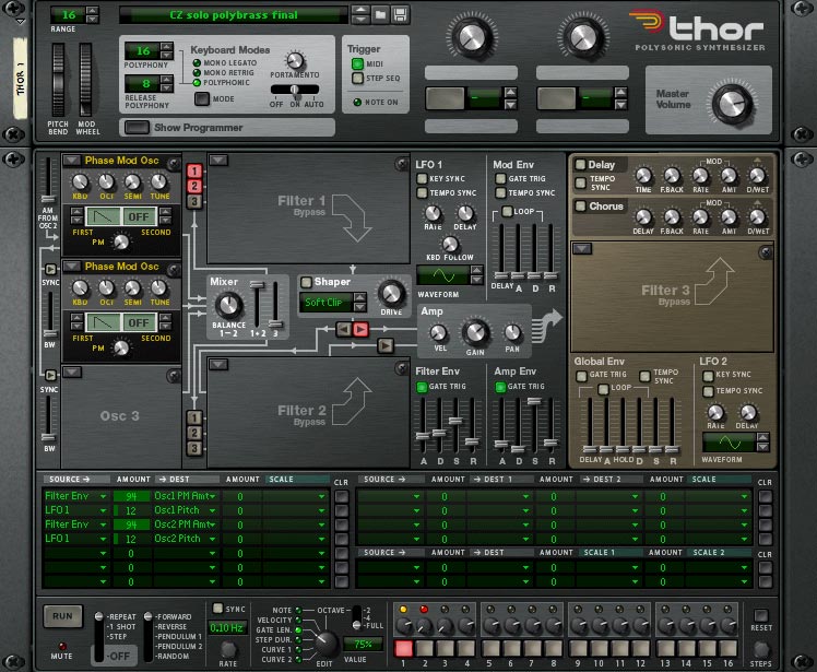
Figure 16: Phase Modulation PolyBrass
Epilogue
You can now manipulate this patch in myriad ways to create a huge range of brassy timbres, including some that are highly reminiscent of orchestral instruments. To demonstrate this, I went back to the single oscillator architecture, reduced the pitch of the PM oscillator by two octaves, shortened the Attack in the Filter Env and reduced the amount of contour applied in the Modulation Matrix. The patch in figure 17, which generated Sound #8, is very little different from that in figure 15, but the brass instrument it imitates is very different. Finally, don't forget that we're doing all of this without invoking a single filter. As I said at the beginning, Phase Modulation is a fabulous method of synthesis, and one that should not be overlooked in Thor:
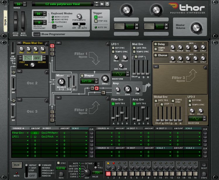
Figure 17: A Phase Modulation tuba
Text & Music by Gordon Reid


